In our previous blog, we discussed some of the basics of M-Bus communications systems, in this blog we will go deeper into the technicalities of M-Bus. We thank Open Metering System Group for the graphics and the valuable information provided.
HOW DOES IT WORK?
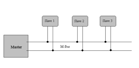
The M-Bus is a serial communication hierarchical system. Is is hierarchical because of the structure of Masters and Slaves. Here the communication controlled by the master (in our previous blog also know and the Gateway, or Data Collection Unit, following a Central Allocation Logic. The M-Bus consists of one master, a number of slaves (meters) and a two-wire connecting cable: see the below. The slaves are connected in parallel to the connecting cable or the Bus.
The standard Voltage on the Bus is 36 Volts DC, which varies to represent a bit by dropping to 24Volts DC, a higher voltage allows for a reduce current.
In order to realize an extensive bus network with a low cost for the transmission medium, a two-wire cable was used together with serial data transfer. In order to allow remote powering of the slaves, the bits on the bus are represented as follows:
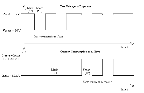
The transfer of bits from master to slave is accomplished by means of voltage level shifts. A logical "1" (Mark) corresponds to a nominal voltage of +36 V at the output of the bus driver (repeater), which is a part of the master; when a logical "0" (Space) is sent, the repeater reduces the bus voltage by 12 V to a nominal +24 V at its output. The transmission of a space by a slave results in a slight reduction in the bus voltage at the repeater due to output impedance. The quiescent (normal) state on the bus is a logical "1" (Mark), i.e. the bus voltage of 36 V at the repeater, and the slaves require a maximum constant quiescent current of 1.5 mA each.
When no slave is sending a space, a constant current will be drained from the repeater which is driving the bus. As a result of this, and also the resistance of the cable, the actual Mark voltage at the slaves may be less than +36 V, depending on the distance between the slave and the repeater and on the total quiescent current of the slaves. The slave therefore does not detect absolute voltage levels, but instead detects a voltage reduction of 12 V.
The repeater adjusts itself to the quiescent current level (Mark), and interprets an increase of the bus current of 11-20 mA as representing a space. This can be realized with acceptable complexity only when the mark state is defined as 36 V. This means that at any instant, transmission is possible in only one direction - either from master to slave, or slave to master (Half Duplex).
As a result of transmission in the master-slave direction with a voltage change of 12 V, and in the answering direction with at least 11 mA; besides the remote powering of the slaves, a high degree of insensitivity to external interference has been achieved.
Segmentation
An M-Bus system can consist of several, so-called, zones, each zone having its own group address, and interconnected via zone controllers and higher-level networks. Each zone consists of segments, which in turn are connected by remote repeaters. Normally, an M-Bus system consists of only a single segment, which is connected via a local repeater or converter to a Computer (PC) or a Data Collection Unit (DCU) acting as master. Such local repeaters convert the M-Bus signals into signals for the communication interface or port on the Data Collection unit.
Cable
A two-wire standard is used as the transmission medium for the M-Bus. When using a telephone cable (JYStY N*2*0.8 mm) The maximum distance between a slave and the repeater is 350 m; this length corresponds to a cable resistance of up to 29 Ohms. Using this maximum resistance as a reference the distance can also be increased using a heavier wire gauge, with an equivalent resistance to up to one Kilometer. However, it is always recommended to keep the distances as short as possible.
While M-Bus already allows Baud rates of up to 38,400 Bauds, this distance applies for the standard configuration having Baud rates between 300 and 9600 Baud, and a maximum of 250 slaves.
The maximum distance can be increased by limiting the Baud rate and using fewer slaves, but the bus voltage in the Space state must at no point in a segment fall below 12 V, because of the remote powering of the slaves. In the standard configuration, the total cable length should not exceed 1000 m, in order to meet the requirement of a maximum cable capacitance of 180 nF.
IN CLOSING;
Whenever you need a Sub-Metering system it is always advisable to consult an expert, who can engineer the project for smooth integration of different utilities with different communication protocols in a seamless and cost-effective way.